A spatial Reuse group is banding together of different OBSS into a common group where common specific Spatial Reuse Group (SRG) OBSS Packet Detect (PD) value can be configured for detection of OBSS packets. By placing the different BSSes in the same channel sense threshold for OBSS transmission, the co-channel interference as seen from the BSSes on each other can be minimized.
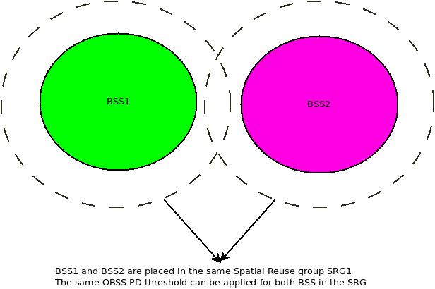
The below diagram illustrates an SRG group:

The above diagram illustrates an example wherein the dotted line indicates the reach of the wireless signal from the respective BSSes. The same OBSS Packet Detect threshold can be applied to the SRG. In addition to the two BSSes shown above in the example, additional BSSes can be added to the group which can use the same OBSS Channel Sense Threshold.
The creation of a Spatial reuse group is a policy decision for the network and different BSSes in the network can be clubbed together to form a Spatial reuse group.
The support for Spatial Reuse Group by an Access Point is provided in the Spatial Reuse Parameter Set element broadcast (optionally) by the Access Point in beacon frames, Probe Response frames, association and re-association frames.
The Spatial Reuse parameter set element is shown below:

The below table outlines some of the parameters in the above element
| Parameter | Description |
| SR Control | Shown below |
| Non-SRG OBSS PD Max offset | contains an unsigned integer that is added to –82 dBm to generate the value of the Non-SRG OBSS PD Max parameter |
| SRG OBSS PD Max offset | contains an unsigned integer that is added to –82 dBm to generate the value of the SRG OBSS PD Max parameter |
| SRG OBSS PD Min Offset | contains an unsigned integer that is added to –82 dBm to generate the value of the SRG OBSS PD Min parameter |
| SRG BSS Color bitmap | The SRG BSS Color Bitmap field is a bitmap that indicates the BSS color values used by members of the SRG. Each bit corresponds to one of 64 BSS colors and hence an SRG group can contain 64 BSSes |
| SRG Partial BSSID Bitmap | A bitmap that indicates the Partial BSSID values used by members of the SRG of which the transmitting STA is a member. Each bit of the bitmap corresponds to one of the 64 possible values of BSSID[39:44], where the lowest numbered bit corresponds to Partial BSSID value 0 and the highest numbered bit corresponds to Partial BSSID value 63. |

The below table outlines the parameters in the above field
| Parameter | Description |
| PSR Disallowed | Indicates whether PSR-based SR transmissions are allowed at non-AP STAs that are associated with the AP that transmitted this element |
| Non-SRG offset Present | Indicates whether the Non-SRG OBSS PD Max Offset field is present in the element |
| SRG information Present | Indicates whether the SRG OBSS PD Min Offset, SRG OBSS PD Max Offset, SRG BSS Color Bitmap, and SRG Partial BSSID Bitmap fields are present in the element |
| HESIGA_spatial_reuse_value15_allowed | ndicates whether non-AP STAs that are associated with the AP that transmitted this element can set the TXVECTOR parameter SPATIAL_REUSE to PSR_AND_NON_SRG_OBSS_PD_PROHIBITED |
| Non-SRG OBSS PD SR disallowed | Indicates whether non-SRG OBSS PD SR transmissions are allowed or not at non-AP STAs that are associated with the AP that transmitted this element |
Pingback: Spatial Reuse Operation | Hitch Hiker's Guide to Learning
Pingback: OBSS Packet Detect Threshold Spatial Reuse | Hitch Hiker's Guide to Learning